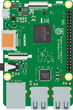
One of the most notable features of the Raspberry Pi is its expansion port, which allows us to interact with the physical world through its GPIO pins (General Purpose Input/Output).
Raspberry Pi has a total of 40 pins, although not all are available for general use. Additionally, some of them have specific functions, such as power, ground, or communication.
The Pinout is a diagram that explains the arrangement of the pins and their specific function. It allows us to know how we can connect sensors, actuators, displays, and other electronic devices.
The pinout follows the same standard across Raspberry Pi models. It is valid for Raspberry Pi 2, 3, 4, and Zero.
So let’s take a detailed look at the Raspberry Pi pinout diagram. In the following tutorials, we will explain the different functionalities 👇.

Leyenda y filtrado
(pulsa los botones para mostrar u ocultar pines)
- POWER
- GPIO
- PWM
- UART
- SPI
- I2C
- COMM
- 3V3 (Pins 1 and 17): Provide 3.3V power. Useful for low-power sensors and devices.
- 5V (Pins 2 and 4): Provide 5V power. Ideal for devices that require more energy.
The Raspberry Pi pins operate at 3.3V. They are not 5V tolerant, so it is necessary to use level converters if connecting 5V devices.
Configuring GPIO Pins
To use the GPIO pins, it is necessary to configure them as inputs or outputs. This can be done using programming languages such as Python with the RPi.GPIO library.
- GPIO (Pins 3, 5, 7, 8, 10, 11, 12, 13, 15, 16, 18, 19, 21, 22, 23, 24, 26, 27, 28, 29, 31, 32, 33, 35, 36, 37, 38, 40): General-purpose pins that can be configured as inputs or outputs.
- PWM (Pin 12): GPIO18 supports PWM output for motor or LED control.
We see it in the entry read more ⯈
Communication with Interfaces
UART (Serial)
The Raspberry Pi has a built-in UART port that allows serial communication with other devices. The GPIO14 (TXD) and GPIO15 (RXD) pins are used to transmit and receive data.
We see it in the entry read more ⯈
I2C
The I2C protocol is used to communicate with sensors and devices that support this interface. The GPIO2 (SDA) and GPIO3 (SCL) pins are used for I2C.
We see it in the entry read more ⯈
SPI
The SPI protocol is useful for devices that require fast and synchronized communication. The GPIO10 (MOSI), GPIO9 (MISO), GPIO11 (SCLK), and GPIO8 (CE0) pins are used for SPI.
We see it in the entry read more ⯈
