What is a thermistor?
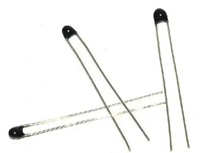
A thermistor is a device whose resistance varies with temperature. We can use this resistance variation to measure the ambient temperature.
A thermistor is made up of a semiconductor such as ferric oxide, nickel oxide, or cobalt oxide. As the temperature increases, the carrier concentration varies, so the resistance of the device varies.
There are two types of thermistors,
- NTC, they have a lower resistance as temperature increases
- PTC, they have a higher resistance as temperature increases (also called a posistor)
with NTC thermistors being more common.
Thermistors are cheap, small, durable, with a relatively wide measurement range, considerably accurate and fast, and not very susceptible to noise. This makes them widely used in temperature measurement in air conditioning, liquid storage, and automotive.
The main disadvantage of thermistors is their strong non-linear behavior. This is not a problem, as we have well-known mathematical models that allow for accurate temperature measurement. However, they force us to necessarily use floating-point numbers and logarithmic calculations, which should be avoided in processors as they significantly slow down execution.
Price
Thermistors are very cheap devices. We can find 10 MF52 thermistors for 1€ from international sellers on eBay, including shipping costs.

How does a thermistor work?
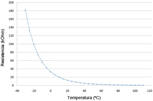
As we have mentioned, the relationship between temperature and resistance in a thermistor is strongly non-linear. The following graph shows this relationship for an MF52 family thermistor with a nominal resistance of 10 kOhm.

Logically, each thermistor family and model presents a different graph, but the behavior is similar.
There are several mathematical models to approximate the behavior of a thermistor, more or less complex. The Steinhart-Hart model is a widely used third-order approximation, given by the following equation,
If we want to include the self-heating correction, we can include the following equation in the model.
Using these equations, the error due to the mathematical model is less than 0.005ºC, for the entire temperature measurement range (from -30 to 110 ºC). Therefore, it introduces an error that is negligible compared to other factors, such as the tolerance of the resistors, the thermistor itself, or floating-point arithmetic.
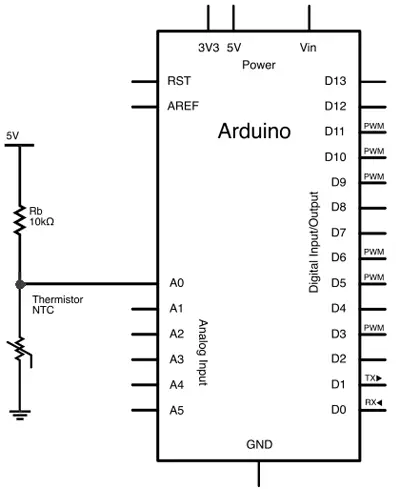
Electrical schematic
The electrical schematic would be as follows.

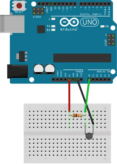
Assembly
For its part, the electrical assembly on a protoboard would be as follows.

Code examples
Below is an example of code. The following code reads the resistance of the thermistor, and uses the Steinhart-Hart equation to calculate the temperature and display it via the serial port.
#include <math.h>

const int Rc = 10000; //value of resistance
const int Vcc = 5;
const int SensorPIN = A0;

float A = 1.11492089e-3;
float B = 2.372075385e-4;
float C = 6.954079529e-8;

float K = 2.5; //dissipation factor in mW/C

void setup()
{
  Serial.begin(9600);
}

void loop()
{
  float raw = analogRead(SensorPIN);
  float V =  raw / 1024 * Vcc;

  float R = (Rc * V ) / (Vcc - V);


  float logR  = log(R);
  float R_th = 1.0 / (A + B * logR + C * logR * logR * logR );

  float kelvin = R_th - V*V/(K * R)*1000;
  float celsius = kelvin - 273.15;

  Serial.print("T = ");
  Serial.print(celsius);
  Serial.print("C\n");
  delay(2500);
}
The A, B, and C values used are calibrated for a 10kOhm MF52 resistance, and should be changed for other types of thermistors.
Sometimes, we can obtain these values directly from the component’s datasheet. However, it is common that only a Beta value is provided, corresponding to a model of lower precision than Steinhart-Hart. In these cases, we must obtain the A, B, and C values by adjusting the resistance and temperature table of the sensor.
Download the code
All the code from this post is available for download on Github.


