What is a TCS3200 color sensor?
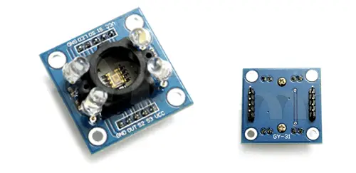
The TCS3200 is an optical sensor that allows detecting the color of an object located in front of it. We can easily connect this sensor to a programmable logic controller or processor such as Arduino.
Internally, the TCS3200 is formed by an array of silicon photodiodes together with a frequency converter, in a single CMOS integrated circuit.
The array has 8 x 8 photodiodes of 110 µm, of which 16 have blue filters, 16 green, 6 red, and 16 have no filter. The photodiodes are distributed in a way that minimizes the effect of non-uniform light incidence.
The output of the TCS3200 is a 50% duty square wave, whose frequency is proportional to the light intensity. The sensor supply voltage is 2.7V to 5.5V.

Frequently, the TCS3200 is distributed in modules that incorporate two or four white light LEDs and a plastic cover. The objective of both measures is to minimize the effects of ambient lighting on the measurement.
Despite its specifications and elements to eliminate ambient light, the TCS3200 is not capable of precisely measuring the RGB color of an object, or the color temperature of a light source.
However, we can use it to distinguish between basic colors. For example, we can use it to recognize the color of a card or an object, and guide a robot on a route.
If you are looking for a color sensor you should look at the TCS34725, a more modern and advanced RGB sensor than the TCS3200. More information in this post.
Price
The TCS3200 is a moderately cheap sensor. We can find modules without the plastic cover for 1.80€ and for about 3€ with the cover, looking at international sellers on eBay or AliExpress.

Mounting scheme
The TCS3200 has four digital inputs S0, S1, S2, and S3, and a digital output Out. To connect it to Arduino we will need to use at least 3 digital pins.
First, we must power the module by connecting the Gnd and Vcc pins of the TCS3200, respectively, to Gnd and Vcc of Arduino.
The S0 and S1 pins control the output frequency and module deactivation. We connect them to two digital outputs, or we can connect them to 5V if we do not want to be able to turn off the module.
| Power down | 2% | 20% | 100% | |
|---|---|---|---|---|
| s0 | L | L | H | H |
| s1 | L | H | L | H |
On the other hand, the S2 and S3 pins select the color to be measured. We must connect them to two digital outputs of Arduino.
| Red | Blue | Clear | Green | |
|---|---|---|---|---|
| s2 | L | L | H | H |
| s3 | L | H | L | H |
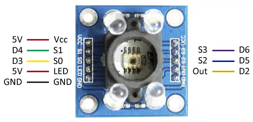
Finally, we connect the sensor output Out to a digital input of Arduino, so the connection using the pins would be as follows.

While the connection, seen from Arduino, would be as follows.
Code examples
In the following example, we read the TCS3200. To do this, we use the PulseIn function to determine the duration of the pulse received by the sensor.
We go through the process for each color, and use the obtained values to classify it as red, blue, or green.
//VCC——5V
//GND——GND
//S0——D3
//S1——D4
//S2——D5
//S3——D6
//OUT——D2

const int s0 = 8;
const int s1 = 9;
const int s2 = 12;
const int s3 = 11;
const int out = 10;

byte countRed = 0;
byte countGreen = 0;
byte countBlue = 0;

void setup() {
  Serial.begin(9600);
  pinMode(s0, OUTPUT);
  pinMode(s1, OUTPUT);
  pinMode(s2, OUTPUT);
  pinMode(s3, OUTPUT);
  pinMode(out, INPUT);
  digitalWrite(s0, HIGH);
  digitalWrite(s1, HIGH);
}

void loop() {
  getColor();
  Serial.print("Red: ");
  Serial.print(countRed, DEC);
  Serial.print("Green: ");
  Serial.print(countGreen, DEC);
  Serial.print("Blue: ");
  Serial.print(countBlue, DEC);

  if (countRed < countBlue && countGreen > 100 && countRed < 80)
  {
    Serial.println(" - Red");
  }
  else if (countBlue < countRed && countBlue < countGreen)
  {
    Serial.println(" - Blue");
  }
  else if (countGreen < countRed && countGreen < countBlue)
  {
    Serial.println(" - Green");
  }
  else {
    Serial.println("-");
  }
  delay(300);
}

void getColor()
{
  digitalWrite(s2, LOW);
  digitalWrite(s3, LOW);
  countRed = pulseIn(out, digitalRead(out) == HIGH ? LOW : HIGH);
  digitalWrite(s3, HIGH);
  countBlue = pulseIn(out, digitalRead(out) == HIGH ? LOW : HIGH);
  digitalWrite(s2, HIGH);
  countGreen = pulseIn(out, digitalRead(out) == HIGH ? LOW : HIGH);
}
Download the code
All the code from this post is available for download on Github.

