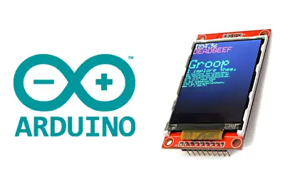
What is a TFT display?
A TFT display is one of the types of screens that can be used in electronic and Arduino projects. The size of these screens generally varies between 1.44” and 3.2” and resolutions of 128x128 to 240x320 pixels.
Like the rest of the screens, a TFT needs a controller that translates the received information into the necessary low-level signals to control the panel’s electronics. This controller will condition the connection scheme and the code that we must use.
Within home electronics, there are several models of TFT and controllers available, with the ST7735 being common for sizes up to 120x160 pixels, and the ILI9341 for sizes up to 240x320 pixels. Other controllers are the ILI9163C, the HX8357 (320X480PX), and the Samsung S6D02A1 (QDTech).
In most cases communication with the TFT screen is done through the SPI bus due to the high volume of data they require. Therefore, they are easy to connect and use from Arduino.
The size and maximum resolution of the screen that we can control are determined by the characteristics of the processor model we are using. In general, handling a TFT screen can be considered at the limit of Arduino’s capabilities as they represent a significant processor and memory load (only the program will occupy around 50% of the available memory).
With an Arduino UNO, Mini, and Pro resolutions larger than 240x320 pixels are not advisable (up to approximately 3.5”). For higher resolutions, such as 320x480 pixels, we will need to use a more powerful processor like the STM32 or the ESP8266. To use larger screens, from 600x800 (7”) onwards, you should consider using another option such as a Raspberry PI.
Many of the available models incorporate an SD or micro SD card reader, accessible through the SPI bus, which can be used to store images that will be displayed on the TFT. There are also models, at a higher price, that incorporate a touch panel. In the case of touch TFT panels, even more so, you should consider using a more powerful option.
Despite the power limitations, these small screens are widely used in a large number of projects as they are an excellent way to display information to the user. Therefore, they are a great alternative to other display types such as the Hitachi HD44780 LCD display or the Nokia 5510 LCD.
Price
The prices of these small TFT screens vary widely depending on their size, which in turn is related to the resolution and the controller.
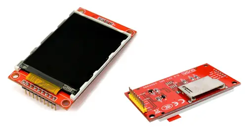
Among the most common, and therefore the cheapest, we can find 2.4” TFT screens with a resolution of 240x320 pixels and the ILI9341 controller for around €3.20, when looking for international sellers on AliExpress.
There are other models with the ILI9341, with sizes from 2.2” to 3.2” and a resolution of 240x320 pixels, at a similar price.
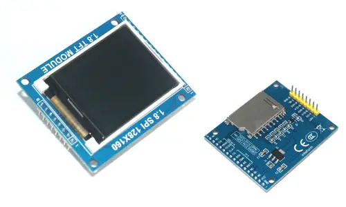
With the ST7735 controller, we can find 1.8” TFT screens with 128x160 pixels for €3.15.
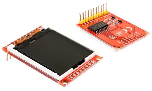
Also with the same ST7735 controller, we find 1.44” screens with 128x128 pixels at a price of €2.6.
Of course, we will also find other types of screens with QDTech, Samsung S6D02A1, or ILI9163C controllers. In general, they tend to be more expensive than the previous screens.
How does a TFT display work?
TFT displays are a variation of LCD (Liquid Crystal Display) screens. In general, an LCD is a glass panel that becomes opaque and its opacity is controlled electrically.
LCD panels do not generate their own light but require a backlight provided by some light source (for example, fluorescent or LED). The LCD panel blocks the emitted light at certain points, allowing an image to be generated.
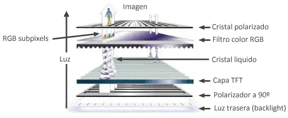
To block the emitted light, it is polarized, and the last layer of the screen has a polarized crystal. The LCD molecules can be electrically aligned to modify the polarization of the light passing through it, “rotating” it as it passes through the crystal. In this way, the opacity level of the LCD panel can be controlled.
In an RGB TFT screen, each pixel has three small LCD cells with color filters that block one of the components of the backlight, generating the image formed by color subpixels.
The TFT technology (Thin Transistor Layer) refers to the electronics necessary to switch the LCD. The subpixels are distributed in a matrix, so that each one is controlled by turning on the corresponding row and column. To avoid the voltage drops produced when powering several pixels in series, each one has a small transistor in a thin layer, which gives rise to the name of this technology.
Connection diagram
The connection of these panels is simple, we simply power the module from Arduino using GND and 5V and connect the TFT data pins with Arduino as we saw in the entry on the SPI bus.
As we saw in this post, the main difficulty is that each manufacturer uses slightly different designations for the pins involved in the SPI bus.
Based on the table we saw in the entry on the SPI bus with common pin designations for different devices, the following table shows the different pins that we will find in the different TFT models, with the equivalence in colors and Arduino pins that we will use in this post.
| Nombre | Alias | Pin (en Arduino Uno o Nano) | Descripcion |
|---|---|---|---|
| VCC | +3.3 … 5 Volt | ||
| GND | Ground | Ground | |
| SCLK | CLK/SCK/SCLK | D13 (hardware) | Clock (SPI) |
| MISO | MISO/SDO/DOUT | D12 (hardware) | Leader In Follower Out (SPI) |
| MOSI | MOSI/SDI/DIN | D11 (hardware) | Leader Out Follower In (SPI) |
| SS | SS/CS/SDA | D10 (hardware, solo en seguidor) | Follower/Chip Select (SPI) |
| RES | RST/RES/REST | D9 (variable, se fija por software) | Controller Reset |
| RS | RS/DC | D8 (variable, se fija por software) | Mode: Command/Data |
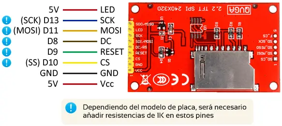
The connection for each TFT screen will depend on both the controller it uses and the details of the module on which it is mounted. As an example, the following diagram shows the connection of a 2.2” 240x320 pixel TFT with ILI9341 controller.
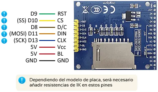
The following diagram shows the connection of a module with a 1.8” 128x160 pixel TFT screen with ST7735 controller.
While in the last example, we have a 1.4” 128x128 pixel TFT module also with ST7735 controller.
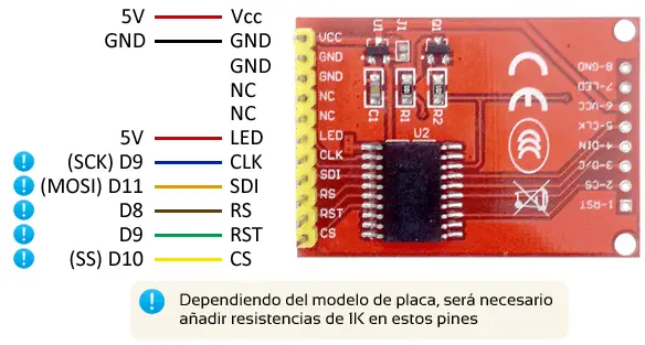
In all cases, the connection from Arduino will be the same, as shown in the following image.
The SPI pins shown are valid for the Arduino Uno, Nano, and Mini Pro models. For other Arduino models, consult the corresponding pinout diagram.
Check that your board is compatible with 5V before connecting it to Arduino. If not, you will have to use a logical level converter, or place 1K resistors to limit the current reaching the TFT screen.
Code examples
To handle the TFT screen, we will need an appropriate library for the type of controller it uses. The following list contains links to libraries for the main TFT controllers.
At the same time, all of these libraries use Adafruit GFX to create graphics easily.
Each library provides code examples, which is advisable to review. All the codes are very similar, as they use the Adafruit GFX library for graphics.
It wouldn’t make much sense to incorporate all of them in the entry. As an example, the following code shows a demo for a 2.2”/2.4” TFT screen with ILI9341 controller and a resolution of 240x340 pixels.
/***************************************************
This is our GFX example for the Adafruit ILI9341 Breakout and Shield
----> http://www.adafruit.com/products/1651

Check out the links above for our tutorials and wiring diagrams
These displays use SPI to communicate, 4 or 5 pins are required to
interface (RST is optional)
Adafruit invests time and resources providing this open source code,
please support Adafruit and open-source hardware by purchasing
products from Adafruit!

Written by Limor Fried/Ladyada for Adafruit Industries.
MIT license, all text above must be included in any redistribution
****************************************************/

#include "SPI.h"
#include "Adafruit_GFX.h"
#include "Adafruit_ILI9341.h"


#define TFT_CS 10

#define TFT_DC 8

// Use hardware SPI (on Uno, #13, #12, #11) and the above for CS/DC
Adafruit_ILI9341 ILI9341 = Adafruit_ILI9341(TFT_CS, TFT_DC);

void setup() {
  Serial.begin(9600);
  Serial.println("ILI9341 Test!");

  ILI9341.begin();

  // read diagnostics (optional but can help debug problems)
  uint8_t x = ILI9341.readcommand8(ILI9341_RDMODE);
  Serial.print("Display Power Mode: 0x"); Serial.println(x, HEX);
  x = ILI9341.readcommand8(ILI9341_RDMADCTL);
  Serial.print("MADCTL Mode: 0x"); Serial.println(x, HEX);
  x = ILI9341.readcommand8(ILI9341_RDPIXFMT);
  Serial.print("Pixel Format: 0x"); Serial.println(x, HEX);
  x = ILI9341.readcommand8(ILI9341_RDIMGFMT);
  Serial.print("Image Format: 0x"); Serial.println(x, HEX);
  x = ILI9341.readcommand8(ILI9341_RDSELFDIAG);
  Serial.print("Self Diagnostic: 0x"); Serial.println(x, HEX);

  Serial.println(F("Benchmark                Time (microseconds)"));

  Serial.print(F("Screen fill              "));
  Serial.println(testFillScreen());
  delay(500);

  Serial.print(F("Text                     "));
  Serial.println(testText());
  delay(3000);

  Serial.print(F("Lines                    "));
  Serial.println(testLines(ILI9341_CYAN));
  delay(500);

  Serial.print(F("Horiz/Vert Lines         "));
  Serial.println(testFastLines(ILI9341_RED, ILI9341_BLUE));
  delay(500);

  Serial.print(F("Rectangles (outline)     "));
  Serial.println(testRects(ILI9341_GREEN));
  delay(500);

  Serial.print(F("Rectangles (filled)      "));
  Serial.println(testFilledRects(ILI9341_YELLOW, ILI9341_MAGENTA));
  delay(500);

  Serial.print(F("Circles (filled)         "));
  Serial.println(testFilledCircles(10, ILI9341_MAGENTA));

  Serial.print(F("Circles (outline)        "));
  Serial.println(testCircles(10, ILI9341_WHITE));
  delay(500);

  Serial.print(F("Triangles (outline)      "));
  Serial.println(testTriangles());
  delay(500);

  Serial.print(F("Triangles (filled)       "));
  Serial.println(testFilledTriangles());
  delay(500);

  Serial.print(F("Rounded rects (outline)  "));
  Serial.println(testRoundRects());
  delay(500);

  Serial.print(F("Rounded rects (filled)   "));
  Serial.println(testFilledRoundRects());
  delay(500);

  Serial.println(F("Done!"));

}

void loop(void) {
  for (uint8_t rotation = 0; rotation<4; rotation++) {
    ILI9341.setRotation(rotation);
    testText();
    delay(1000);
  }
}

unsigned long testFillScreen() {
  unsigned long start = micros();
  ILI9341.fillScreen(ILI9341_BLACK);
  ILI9341.fillScreen(ILI9341_RED);
  ILI9341.fillScreen(ILI9341_GREEN);
  ILI9341.fillScreen(ILI9341_BLUE);
  ILI9341.fillScreen(ILI9341_BLACK);
  return micros() - start;
}

unsigned long testText() {
  ILI9341.fillScreen(ILI9341_BLACK);
  unsigned long start = micros();
  ILI9341.setCursor(0, 0);
  ILI9341.setTextColor(ILI9341_WHITE);  ILI9341.setTextSize(1);
  ILI9341.println("Hello World!");
  ILI9341.setTextColor(ILI9341_YELLOW); ILI9341.setTextSize(2);
  ILI9341.println(1234.56);
  ILI9341.setTextColor(ILI9341_RED);    ILI9341.setTextSize(3);
  ILI9341.println(0xDEADBEEF, HEX);
  ILI9341.println();
  ILI9341.setTextColor(ILI9341_GREEN);
  ILI9341.setTextSize(5);
  ILI9341.println("Groop");
  ILI9341.setTextSize(2);
  ILI9341.println("I implore thee,");
  ILI9341.setTextSize(1);
  ILI9341.println("my foonting turlingdromes.");
  ILI9341.println("And hooptiously drangle me");
  ILI9341.println("with crinkly bindlewurdles,");
  ILI9341.println("Or I will rend thee");
  ILI9341.println("in the gobberwarts");
  ILI9341.println("with my blurglecruncheon,");
  ILI9341.println("see if I don't!");
  return micros() - start;
}

unsigned long testLines(uint16_t color) {
  unsigned long start, t;
  int           x1, y1, x2, y2,
    w = ILI9341.width(),
    h = ILI9341.height();

  ILI9341.fillScreen(ILI9341_BLACK);

  x1 = y1 = 0;
  y2 = h - 1;
  start = micros();
  for (x2 = 0; x2<w; x2 += 6) ILI9341.drawLine(x1, y1, x2, y2, color);
  x2 = w - 1;
  for (y2 = 0; y2<h; y2 += 6) ILI9341.drawLine(x1, y1, x2, y2, color);
  t = micros() - start; // fillScreen doesn't count against timing

  ILI9341.fillScreen(ILI9341_BLACK);

  x1 = w - 1;
  y1 = 0;
  y2 = h - 1;
  start = micros();
  for (x2 = 0; x2<w; x2 += 6) ILI9341.drawLine(x1, y1, x2, y2, color);
  x2 = 0;
  for (y2 = 0; y2<h; y2 += 6) ILI9341.drawLine(x1, y1, x2, y2, color);
  t += micros() - start;

  ILI9341.fillScreen(ILI9341_BLACK);

  x1 = 0;
  y1 = h - 1;
  y2 = 0;
  start = micros();
  for (x2 = 0; x2<w; x2 += 6) ILI9341.drawLine(x1, y1, x2, y2, color);
  x2 = w - 1;
  for (y2 = 0; y2<h; y2 += 6) ILI9341.drawLine(x1, y1, x2, y2, color);
  t += micros() - start;

  ILI9341.fillScreen(ILI9341_BLACK);

  x1 = w - 1;
  y1 = h - 1;
  y2 = 0;
  start = micros();
  for (x2 = 0; x2<w; x2 += 6) ILI9341.drawLine(x1, y1, x2, y2, color);
  x2 = 0;
  for (y2 = 0; y2<h; y2 += 6) ILI9341.drawLine(x1, y1, x2, y2, color);

  return micros() - start;
}

unsigned long testFastLines(uint16_t color1, uint16_t color2) {
  unsigned long start;
  int           x, y, w = ILI9341.width(), h = ILI9341.height();

  ILI9341.fillScreen(ILI9341_BLACK);
  start = micros();
  for (y = 0; y<h; y += 5) ILI9341.drawFastHLine(0, y, w, color1);
  for (x = 0; x<w; x += 5) ILI9341.drawFastVLine(x, 0, h, color2);

  return micros() - start;
}

unsigned long testRects(uint16_t color) {
  unsigned long start;
  int           n, i, i2,
    cx = ILI9341.width() / 2,
    cy = ILI9341.height() / 2;

  ILI9341.fillScreen(ILI9341_BLACK);
  n = min(ILI9341.width(), ILI9341.height());
  start = micros();
  for (i = 2; i<n; i += 6) {
    i2 = i / 2;
    ILI9341.drawRect(cx - i2, cy - i2, i, i, color);
  }

  return micros() - start;
}

unsigned long testFilledRects(uint16_t color1, uint16_t color2) {
  unsigned long start, t = 0;
  int           n, i, i2,
    cx = ILI9341.width() / 2 - 1,
    cy = ILI9341.height() / 2 - 1;

  ILI9341.fillScreen(ILI9341_BLACK);
  n = min(ILI9341.width(), ILI9341.height());
  for (i = n; i>0; i -= 6) {
    i2 = i / 2;
    start = micros();
    ILI9341.fillRect(cx - i2, cy - i2, i, i, color1);
    t += micros() - start;
    // Outlines are not included in timing results
    ILI9341.drawRect(cx - i2, cy - i2, i, i, color2);
  }

  return t;
}

unsigned long testFilledCircles(uint8_t radius, uint16_t color) {
  unsigned long start;
  int x, y, w = ILI9341.width(), h = ILI9341.height(), r2 = radius * 2;

  ILI9341.fillScreen(ILI9341_BLACK);
  start = micros();
  for (x = radius; x<w; x += r2) {
    for (y = radius; y<h; y += r2) {
      ILI9341.fillCircle(x, y, radius, color);
    }
  }

  return micros() - start;
}

unsigned long testCircles(uint8_t radius, uint16_t color) {
  unsigned long start;
  int           x, y, r2 = radius * 2,
    w = ILI9341.width() + radius,
    h = ILI9341.height() + radius;

  // Screen is not cleared for this one -- this is
  // intentional and does not affect the reported time.
  start = micros();
  for (x = 0; x<w; x += r2) {
    for (y = 0; y<h; y += r2) {
      ILI9341.drawCircle(x, y, radius, color);
    }
  }

  return micros() - start;
}

unsigned long testTriangles() {
  unsigned long start;
  int           n, i, cx = ILI9341.width() / 2 - 1,
    cy = ILI9341.height() / 2 - 1;

  ILI9341.fillScreen(ILI9341_BLACK);
  n = min(cx, cy);
  start = micros();
  for (i = 0; i<n; i += 5) {
    ILI9341.drawTriangle(
      cx, cy - i, // peak
      cx - i, cy + i, // bottom left
      cx + i, cy + i, // bottom right
      ILI9341.color565(0, 0, i));
  }

  return micros() - start;
}

unsigned long testFilledTriangles() {
  unsigned long start, t = 0;
  int           i, cx = ILI9341.width() / 2 - 1,
    cy = ILI9341.height() / 2 - 1;

  ILI9341.fillScreen(ILI9341_BLACK);
  start = micros();
  for (i = min(cx, cy); i>10; i -= 5) {
    start = micros();
    ILI9341.fillTriangle(cx, cy - i, cx - i, cy + i, cx + i, cy + i,
      ILI9341.color565(0, i, i));
    t += micros() - start;
    ILI9341.drawTriangle(cx, cy - i, cx - i, cy + i, cx + i, cy + i,
      ILI9341.color565(i, i, 0));
  }

  return t;
}

unsigned long testRoundRects() {
  unsigned long start;
  int           w, i, i2,
    cx = ILI9341.width() / 2 - 1,
    cy = ILI9341.height() / 2 - 1;

  ILI9341.fillScreen(ILI9341_BLACK);
  w = min(ILI9341.width(), ILI9341.height());
  start = micros();
  for (i = 0; i<w; i += 6) {
    i2 = i / 2;
    ILI9341.drawRoundRect(cx - i2, cy - i2, i, i, i / 8, ILI9341.color565(i, 0, 0));
  }

  return micros() - start;
}

unsigned long testFilledRoundRects() {
  unsigned long start;
  int           i, i2,
    cx = ILI9341.width() / 2 - 1,
    cy = ILI9341.height() / 2 - 1;

  ILI9341.fillScreen(ILI9341_BLACK);
  start = micros();
  for (i = min(ILI9341.width(), ILI9341.height()); i>20; i -= 6) {
    i2 = i / 2;
    ILI9341.fillRoundRect(cx - i2, cy - i2, i, i, i / 8, ILI9341.color565(0, i, 0));
  }

  return micros() - start;
}
Result
Here is a video showing the result of running one of the examples.
