We continue with 3D printing. After having seen some posts about the Anycubic i3 Mega, it’s time to get down to business and properly start the tutorials with a basic guide to 3D printing.
In this post, we will see the general process of 3D printing. Furthermore, it will serve to introduce some of the terms that will appear as we delve into the world of 3D.
It’s important to keep in mind that, in reality, our domestic 3D printer is a relatively “dumb” machine that only knows “go to such position” and “deposit so much material”. It has no more logic or intelligence.
Therefore, there is a whole process from having the idea to having the manufactured part, with various stages involved. Broadly speaking, the process for a printer like the one we will use follows the following diagram.

Seems like a lot of hassle? Well, actually it’s a pretty simple process. Once we’ve done it a few times, we’ll have completely lost our fear of it and will be able to do it with our eyes closed.
In future posts, we will see each of the parts that make up the process in detail. But for now, let’s warm up by looking at it globally in this basic introduction guide to 3D printing.
Your Idea
It might sound a bit romantic, but in most cases the process starts with your idea. It could be a need, a crazy idea, a toy design, a replacement for a broken part.
Of all the things you can do with a 3D printer, the most fun, interesting, and rewarding projects you will print are those that come from your own head.
Having a 3D printer gives you enormous freedom to fabricate your own parts. And not just conventional parts; 3D printing opens a door to parts almost impossible to manufacture by other methods, and at a very reduced price.
So you know. Take advantage of it, and enjoy it!
3D Drawing Software
Ideas are beautiful, but printers don’t print ideas. You will need to draw it in 3D, and for that, you will need 3D drawing software.
There is a wide variety of 3D drawing software available. We will frequently use CAD software (so to speak, the more “technical” branch of 3D drawing), but there are other alternatives like mesh modeling or sculpting tools.
Within CAD software, as we said the most used type of program for drawing your idea, we have many commercial alternatives (SolidWorks, SolidEdge, Inventor), some free for educational use (Fusion 360), and even Open Source (FreeCAD).

In general, drawing software each use their own file type, and our printer is not able to read them. Therefore, it is necessary to export to a common format, understood by the next steps in the process.
Export to STL
The common format that we will predominantly use is STL (Standard Triangle Language) created by the company 3D Systems for the rapid prototyping industry.
As its name indicates, the STL format saves triangular meshes. But CAD software normally works with curves and surfaces represented mathematically, with (almost) infinite precision.
Therefore, during export, the CAD software must convert these perfect curves and surfaces into polygons and triangles.

Here we have a compromise between file size and precision. If we want the approximation to be very precise, we will need millions of triangles and the file will be heavy, complicating its subsequent processing. If, on the contrary, we use a very low number of triangles, there will be a big difference between the polygonal approximation and the curves.
Alternative: Download STL from the Internet
A very common alternative to drawing our own 3D file is to download a design directly from the Internet, made by the user community and freely shared, of course.
With the rise of 3D printing, there are many web platforms where users share their designs, already in STL format, with other users. Probably the most well-known is Thingiverse, although there are others like Github, TinkerCAd, Pinshape, Yeggi, 3dmag.
Downloading STL files is a great way to get models ready to print. Because, and I’ll get romantic again, if having an idea is great, a community of users sharing ideas is unstoppable.
Slicer Software
We already have our triangulated 3D model in STL format, either because we drew our file and exported it to STL, or because we downloaded one directly from the internet.
But our 3D printer still doesn’t understand this 3D model. As we said, it only understands trajectories and positions. How do we convert our STL into something our printer can understand?
This is where the Slicer software comes in, which in Spanish would translate to “slicer” software, and it is one of the most important parts of the 3D printing process.
The function of the Slicer is to divide our 3D object into layers at different heights, which is what we will actually have when printing the part. For each layer, it calculates the trajectories the print head must follow to perform the printing.

The Slicer performs all the “heavy” calculation of the printing. It takes into account the parameters of our printer and filament, which we must adjust carefully. The quality of our part will largely depend on these parameters.
Furthermore, the Slicer has other additional functions, such as defining the size and orientation of the part, splitting or grouping objects, or printing several objects in a single process.
There are many Slicer programs. Perhaps the most well-known is Cura from Ultimaker, which is Open Source. Other Open Source Slicer software includes Slic3r or IdeaMaker, (among many others), and there are also proprietary (paid) software like Simplify 3D, Netfabb.
Generate the GCode
The result of the Slicer’s calculation is a GCode file. The GCode file is a text file with a format widely used in CNC machines.
If we edit the GCode file, we will see thousands and thousands of lines that look like this:
G1 X95.622 Y93.385 E0.06435 G1 X96.148 Y93.098 E0.09425 G1 X97.089 Y92.652 E0.1462 G1 X97.687 Y92.413 E0.17833 G1 X98.608 Y92.199 E0.2255
These are the movement instructions and coordinates to which the 3D printer must move the print head to print our part. The GCode has commands to move the head in X, Y, Z, extrude an amount of filament, change temperature… the entire program to print the part.
The GCode can indeed be interpreted by our 3D printer. But we still have to get it from the computer to the 3D printer. We have several options.
The first and easiest option to move the GCode to our printer is to use an SD card or a USB memory stick. Most printers have one or both options and can autonomously print the GCode file we insert.
It might seem very cumbersome to have to go back and forth with a card, but, in reality, it is a very used, simple, and convenient option.
Another, somewhat more advanced option is to use a Printing Host, that is, a computer connected to the 3D printer via a USB port that controls the printing process at all times.
There are specific programs for 3D Printing Hosts, the most famous being Octoprint, Astroprint or Repetier Server, which can be run on a mini pc like a Raspberry Pi.
In addition to being able to send GCode via Wifi to our 3D printer, having a 3D Printing Host has additional advantages, such as integrating the Slicer software, real-time 3D printing supervision, or viewing the process with a WebCam.
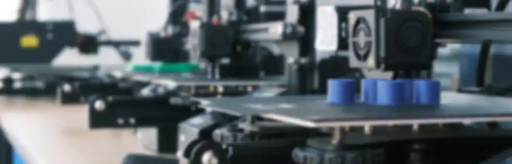
3D Printer
Whether via a mini SD card, a USB memory stick, or a Host, we now have the GCode file on our printer! But how does our printer convert that bunch of lines with coordinates into a printed part?
Time to briefly see how the printer works, although we will see each part in more detail in upcoming posts.
Very briefly, our printer has a structure (base, gantry, bed), mechanical parts (motors, pulleys, etc.), and an electronic part. The electronic part is the brain of our printer.
The electronic part is usually based on a board similar to or derived from an Arduino. This board controls the movement of the motors and makes them follow the GCode instructions.
Of course, to do its job, the electronic board has to run a program (and not a small one, precisely). This is where the firmware comes in.
The firmware is the software that runs the electronics of your 3D printer, the “intelligence” of your printer. The firmware takes the GCode and is responsible for executing the actions that appear in it.
The firmware controls all the components of the 3D printer. But, in addition, it can perform modifications like limiting the speed or acceleration of the print head.
It shouldn’t surprise us that there are also several firmware for printers. The most well-known is Marlin, and many of the others are derived from or based on it. Marlin, in turn, is based on Sprinter and Grbl.
Other examples are MK4duo, Sailfish, Repetier-Firmware, or RepRap-Firmware. Most are Open Source, so we can even make modifications ourselves.
We can overwrite or update the printer’s firmware, but not all firmware are compatible with all printers. In general, we should only touch the firmware if we know what we are doing.
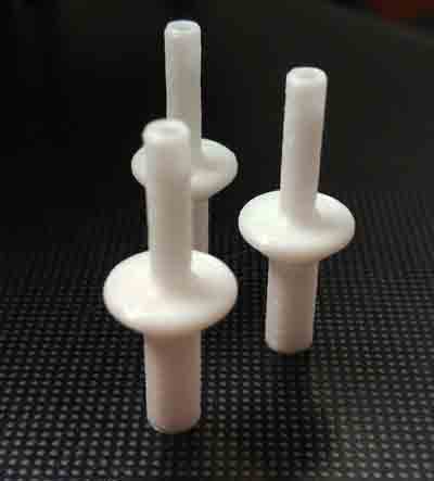
Printed Part
And we’ve reached the end! If the whole process went correctly, we will have a printed part (or several). If it didn’t go correctly, we’ll have a plate of plastic spaghetti.
This is, in summary, the general picture of the 3D printing process. In future posts, we will delve deeper into each of the points we’ve seen, learn to design parts, and common errors and how to fix them. See you soon!