¿Qué es un IMU MPU-6050?
El MPU-6050 es una unidad de medición inercial (IMU) de seis grados de libertad (6DOF) fabricado por Invensense, que combina un acelerómetro de 3 ejes y un giroscopio de 3 ejes.
La comunicación puede realizarse tanto por SPI como por bus I2C, por lo que es sencillo obtener los datos medidos. La tensión de alimentación es de bajo voltaje entre 2.4 a 3.6V.
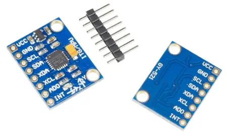
Frecuentemente se encuentran integrados en módulos como el GY-521 que incorporan la electrónica necesaria para conectarla de forma sencilla a un Arduino. En la mayoría de los módulos, esto incluye un regulador de voltaje que permite alimentar directamente a 5V.
Dispone de conversores analógicos digitales (ADC) de 16bits. El rango del acelerómetro puede ser ajustado a ±2g, ±4g, ±8g, y ±16g, el del giroscopio a ±250, ±500, ±1000, and ±2000°/sec.
Es un sensor consume 3.5mA, con todos los sensores y el DMP activados. Dispone de un sensor de temperatura embebido, un reloj de alta precisión e interrupciones programables. También puede conectarse a otros dispositivos I2C como master.
El MPU-6050 incorpora un procesador interno (DMP Digital Motion Processor) que ejecuta complejos algortimos de MotionFusion para combinar las mediciones de los sensores internos, evitando tener que realizar los filtros de forma exterior.
El MPU-6050 es uno de los IMUs más empleados por su gran calidad y precio. Será uno de los componentes que con mayor frecuencia incorporaremos a nuestros proyectos de electrónica y robótica.
Si quieres saber más sobre acelerómetros, giroscopios e IMU’s en Arduino consulta las serie de entradas Cómo usar un acelerómetro con Arduino, Cómo usar un giroscopio con Arduino y Medir la inclinación con IMU.
Precio
El MPU-6050 es un sensor excelente en realidad precio debido, entre otros factores, a que es ampliamente utilizado y esto ha permitido reducir su precio.

Podemos encontrarlo en placas de montaje como la GY-521, que incorpora la electrónica necesaria para conectarlo de forma sencilla a Arduino, por 1.10 € en vendedores internacionales de eBay o AliExpress.
Esquema montaje
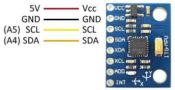
La conexión es sencilla, simplemente alimentamos el módulo desde Arduino mediante GND y 5V y conectamos el pin SDA y SCL de Arduino con los pines correspondientes del sensor.

Mientras que la conexión vista desde el lado de Arduino quedaría así.
En Arduino Uno, Nano y Mini Pro, SDA es el pin A4 y el SCK el pin A5. Para otros modelos de Arduino consultar el esquema patillaje correspondiente.
Verificar que vuestra placa es compatible con 5V antes de conectarla a Arduino. Si no, tendréis que usar un adaptador de nivel lógico.
Ejemplos de código
Para realizar la lectura del MPU-6050 usaremos la librería desarrollada por Jeff Rowberg disponible en este enlace. También emplearemos la librería I2Cdev desarrollada por el mismo autor, que mejora la comunicación I2C.
La librería proporciona ejemplos de código, que resulta aconsejable revisar. Los siguientes ejemplos son modificaciones a partir de los disponibles en la librería.
Leer valores RAW
En el primer ejemplo, aprendemos a leer los valores directamente proporcionados por el MPU-6050 (valores RAW) a través del bus I2C. Los valores RAW tienen un rango de medición entre -32768 y +32767.
//GND - GND
//VCC - VCC
//SDA - Pin A4
//SCL - Pin A5

#include "I2Cdev.h"
#include "MPU6050.h"
#include "Wire.h"

const int mpuAddress = 0x68;  //Puede ser 0x68 o 0x69
MPU6050 mpu(mpuAddress);

int ax, ay, az;
int gx, gy, gz;

void printTab()
{
  Serial.print(F("\t"));
}

void printRAW()
{
  Serial.print(F("a[x y z] g[x y z]:t"));
  Serial.print(ax); printTab();
  Serial.print(ay); printTab();
  Serial.print(az); printTab();
  Serial.print(gx); printTab();
  Serial.print(gy); printTab();
  Serial.println(gz);
}

void setup()
{
  Serial.begin(9600);
  Wire.begin();
  mpu.initialize();
  Serial.println(mpu.testConnection() ? F("IMU iniciado correctamente") : F("Error al iniciar IMU"));
}

void loop()
{
  // Leer las aceleraciones y velocidades angulares
  mpu.getAcceleration(&ax, &ay, &az);
  mpu.getRotation(&gx, &gy, &gz);

  printRAW();

  delay(100);
}
Leer valores en Sistema Internacional
En el siguiente ejemplo aplicamos una escala a los valores RAW para obtener mediciones con significado físico. En el ejemplo, emplearemos valores G para la aceleración, y º/S para la velocidad angular. Con facilidad podréis modificar el código para que proporcione los valores en unidades del Sistema Internacional.
El escalado dependerá del rango de medición que seleccionemos en el MPU-6050, que recordamos puede ser 2g/4g/8g/16g para el acelerómetro y 250/500/1000/2000 (°/s) para el giroscopio.
//GND - GND
//VCC - VCC
//SDA - Pin A4
//SCL - Pin A5

#include "I2Cdev.h"
#include "MPU6050.h"
#include "Wire.h"

const int mpuAddress = 0x68;  // Puede ser 0x68 o 0x69
MPU6050 mpu(mpuAddress);

int ax, ay, az;
int gx, gy, gz;


// Factores de conversion
const float accScale = 2.0 * 9.81 / 32768.0;
const float gyroScale = 250.0 / 32768.0;

void printTab()
{
   Serial.print(F("\t"));
}

// Mostrar medidas en Sistema Internacional
void printRAW()
{
   Serial.print(F("a[x y z] (m/s2) g[x y z] (deg/s):t"));
   Serial.print(ax * accScale); printTab();
   Serial.print(ay * accScale); printTab();
   Serial.print(az * accScale); printTab();
   Serial.print(gx * gyroScale);  printTab();
   Serial.print(gy * gyroScale);  printTab();
   Serial.println(gz * gyroScale);
}

void setup()
{
   Serial.begin(9600);
   Wire.begin();
   mpu.initialize();
   Serial.println(mpu.testConnection() ? F("IMU iniciado correctamente") : F("Error al iniciar IMU"));
}

void loop()
{
   // Leer las aceleraciones y velocidades angulares
   mpu.getAcceleration(&ax, &ay, &az);
   mpu.getRotation(&gx, &gy, &gz);

   printRAW();

   delay(100);
}
Leer inclinación con acelerómetro
En el siguiente ejemplo, calculamos la inclinación del MPU-6050 mediante la proyección de la medición de la gravedad y las relaciones trigonométricas que vimos en la entrada Cómo usar un acelerómetro con Arduino.
//GND - GND
//VCC - VCC
//SDA - Pin A4
//SCL - Pin A5

#include "I2Cdev.h"
#include "MPU6050.h"
#include "Wire.h"

const int mpuAddress = 0x68;  // Puede ser 0x68 o 0x69
MPU6050 mpu(mpuAddress);

int ax, ay, az;
int gx, gy, gz;

void setup()
{
  Serial.begin(9600);
  Wire.begin();
  mpu.initialize();
  Serial.println(mpu.testConnection() ? F("IMU iniciado correctamente") : F("Error al iniciar IMU"));
}

void loop()
{
  // Leer las aceleraciones
  mpu.getAcceleration(&ax, &ay, &az);

  //Calcular los angulos de inclinacion
  float accel_ang_x = atan(ax / sqrt(pow(ay, 2) + pow(az, 2)))*(180.0 / 3.14);
  float accel_ang_y = atan(ay / sqrt(pow(ax, 2) + pow(az, 2)))*(180.0 / 3.14);

  // Mostrar resultados
  Serial.print(F("Inclinacion en X: "));
  Serial.print(accel_ang_x);
  Serial.print(F("\tInclinacion en Y:"));
  Serial.println(accel_ang_y);
  delay(10);
}
Obtener orientación con giroscopio
En el siguiente ejemplo, realizamos la integración de la señal de la velocidad del giroscopio para obtener la orientación del MPU-6050, como vimos en la entrada Cómo usar un giroscopio con Arduino.
//GND - GND
//VCC - VCC
//SDA - Pin A4
//SCL - Pin A5

#include "I2Cdev.h"
#include "MPU6050.h"
#include "Wire.h"

const int mpuAddress = 0x68;  // Puede ser 0x68 o 0x69
MPU6050 mpu(mpuAddress);

int ax, ay, az;
int gx, gy, gz;

long tiempo_prev, dt;
float girosc_ang_x, girosc_ang_y;
float girosc_ang_x_prev, girosc_ang_y_prev;

void updateGiro()
{
  dt = millis() - tiempo_prev;
  tiempo_prev = millis();

  girosc_ang_x = (gx / 131)*dt / 1000.0 + girosc_ang_x_prev;
  girosc_ang_y = (gy / 131)*dt / 1000.0 + girosc_ang_y_prev;

  girosc_ang_x_prev = girosc_ang_x;
  girosc_ang_y_prev = girosc_ang_y;
}

void setup()
{
  Serial.begin(9600);
  Wire.begin();
  mpu.initialize();
  Serial.println(mpu.testConnection() ? F("IMU iniciado correctamente") : F("Error al iniciar IMU"));
}

void loop()
{
  // Leer las velocidades angulares
  mpu.getRotation(&gx, &gy, &gz);

  updateGiro();

  // Mostrar resultados
  Serial.print(F("Rotacion en X:  "));
  Serial.print(girosc_ang_x);
  Serial.print(F("\tRotacion en Y: "));
  Serial.println(girosc_ang_y);

  delay(10);
}
Obtener la orientación con filtro complementario
Este ejemplo empleamos un filtro complementario para combinar la señal del acelerómetro y giroscopio para obtener una mejor medición de la orientación del MPU-6050, como vimos en la entrada Medir la inclinación de un IMU con Arduino y filtro complementario
//GND - GND
//VCC - VCC
//SDA - Pin A4
//SCL - Pin A5

#include "I2Cdev.h"
#include "MPU6050.h"
#include "Wire.h"

const int mpuAddress = 0x68;  // Puede ser 0x68 o 0x69
MPU6050 mpu(mpuAddress);

int ax, ay, az;
int gx, gy, gz;

long tiempo_prev;
float dt;
float ang_x, ang_y;
float ang_x_prev, ang_y_prev;

void updateFiltered()
{
  dt = (millis() - tiempo_prev) / 1000.0;
  tiempo_prev = millis();

  //Calcular los ángulos con acelerometro
  float accel_ang_x = atan(ay / sqrt(pow(ax, 2) + pow(az, 2)))*(180.0 / 3.14);
  float accel_ang_y = atan(-ax / sqrt(pow(ay, 2) + pow(az, 2)))*(180.0 / 3.14);

  //Calcular angulo de rotación con giroscopio y filtro complementario
  ang_x = 0.98*(ang_x_prev + (gx / 131)*dt) + 0.02*accel_ang_x;
  ang_y = 0.98*(ang_y_prev + (gy / 131)*dt) + 0.02*accel_ang_y;

  ang_x_prev = ang_x;
  ang_y_prev = ang_y;
}

void setup()
{
  Serial.begin(9600);
  Wire.begin();
  mpu.initialize();
  Serial.println(mpu.testConnection() ? F("IMU iniciado correctamente") : F("Error al iniciar IMU"));
}

void loop()
{
  // Leer las aceleraciones y velocidades angulares
  mpu.getAcceleration(&ax, &ay, &az);
  mpu.getRotation(&gx, &gy, &gz);

  updateFiltered();

  Serial.print(F("Rotacion en X:  "));
  Serial.print(ang_x);
  Serial.print(F("\t Rotacion en Y: "));
  Serial.println(ang_y);

  delay(10);
}
Obtener la orientación mediante el DMP
En este último ejemplo empleamos el DMP integrado en el MPU-6050 para realizar la combinación de la medición del acelerómetro y el giroscopio, lo que proporciona mejor resultados que emplear un filtro complementario, y además libera a Arduino del proceso de cálculo.
Para que el ejemplo funcione es necesario conectar el pin INT del MPU6050 a un pin con interrupciones (en el ejemplo, con Arduino UNO o Nano, conectar al Pin 2).
//GND - GND
//VCC - VCC
//SDA - Pin A4
//SCL - Pin A5
//INT - Pin 2

#include "I2Cdev.h"
#include "MPU6050_6Axis_MotionApps20.h"

#if I2CDEV_IMPLEMENTATION == I2CDEV_ARDUINO_WIRE
    #include "Wire.h"

#endif

// class default I2C address is 0x68
// specific I2C addresses may be passed as a parameter here
// AD0 low = 0x68
// AD0 high = 0x69
MPU6050 mpu;
//MPU6050 mpu(0x69); // <-- use for AD0 high


#define INTERRUPT_PIN 2

#define LED_PIN 13
bool blinkState = false;

// MPU control/status vars
bool dmpReady = false;  // set true if DMP init was successful
uint8_t mpuIntStatus;   // holds actual interrupt status byte from MPU
uint8_t devStatus;      // return status after each device operation (0 = success, !0 = error)
uint16_t packetSize;    // expected DMP packet size (default is 42 bytes)
uint16_t fifoCount;     // count of all bytes currently in FIFO
uint8_t fifoBuffer[64]; // FIFO storage buffer

Quaternion q;           // [w, x, y, z]
VectorInt16 aa;         // [x, y, z]
VectorInt16 aaReal;     // [x, y, z]
VectorInt16 aaWorld;    // [x, y, z]
VectorFloat gravity;    // [x, y, z]
float ypr[3];           // [yaw, pitch, roll]

volatile bool mpuInterrupt = false;
void dmpDataReady() {
    mpuInterrupt = true;
}

void setup() {
    // join I2C bus (I2Cdev library doesn't do this automatically)
    #if I2CDEV_IMPLEMENTATION == I2CDEV_ARDUINO_WIRE
        Wire.begin();
        Wire.setClock(400000); // 400kHz I2C clock. Comment this line if having compilation difficulties
    #elif I2CDEV_IMPLEMENTATION == I2CDEV_BUILTIN_FASTWIRE
        Fastwire::setup(400, true);
    #endif

    Serial.begin(9600);

    // Iniciar MPU6050
    Serial.println(F("Initializing I2C devices..."));
    mpu.initialize();
    pinMode(INTERRUPT_PIN, INPUT);

    // Comprobar  conexion
    Serial.println(F("Testing device connections..."));
    Serial.println(mpu.testConnection() ? F("MPU6050 connection successful") : F("MPU6050 connection failed"));

    // Iniciar DMP
    Serial.println(F("Initializing DMP..."));
    devStatus = mpu.dmpInitialize();

    // Valores de calibracion
    mpu.setXGyroOffset(220);
    mpu.setYGyroOffset(76);
    mpu.setZGyroOffset(-85);
    mpu.setZAccelOffset(1688);

    // Activar DMP
    if (devStatus == 0) {
        Serial.println(F("Enabling DMP..."));
        mpu.setDMPEnabled(true);

        // Activar interrupcion
        attachInterrupt(digitalPinToInterrupt(INTERRUPT_PIN), dmpDataReady, RISING);
        mpuIntStatus = mpu.getIntStatus();

        Serial.println(F("DMP ready! Waiting for first interrupt..."));
        dmpReady = true;

        // get expected DMP packet size for later comparison
        packetSize = mpu.dmpGetFIFOPacketSize();
    } else {
        // ERROR!
        // 1 = initial memory load failed
        // 2 = DMP configuration updates failed
        // (if it's going to break, usually the code will be 1)
        Serial.print(F("DMP Initialization failed (code "));
        Serial.print(devStatus);
        Serial.println(F(")"));
    }
}

void loop() {
    // Si fallo al iniciar, parar programa
    if (!dmpReady) return;

    // Ejecutar mientras no hay interrupcion
    while (!mpuInterrupt && fifoCount < packetSize) {
        // AQUI EL RESTO DEL CODIGO DE TU PROGRRAMA
    }

    mpuInterrupt = false;
    mpuIntStatus = mpu.getIntStatus();

    // Obtener datos del FIFO
    fifoCount = mpu.getFIFOCount();

    // Controlar overflow
    if ((mpuIntStatus & 0x10) || fifoCount == 1024) {
        mpu.resetFIFO();
        Serial.println(F("FIFO overflow!"));
    }
    else if (mpuIntStatus & 0x02) {
        // wait for correct available data length, should be a VERY short wait
        while (fifoCount < packetSize) fifoCount = mpu.getFIFOCount();

        // read a packet from FIFO
        mpu.getFIFOBytes(fifoBuffer, packetSize);

        // track FIFO count here in case there is > 1 packet available
        // (this lets us immediately read more without waiting for an interrupt)
        fifoCount -= packetSize;

  // MMostrar Yaw, Pitch, Roll
  mpu.dmpGetQuaternion(&q, fifoBuffer);
  mpu.dmpGetGravity(&gravity, &q);
  mpu.dmpGetYawPitchRoll(ypr, &q, &gravity);
  Serial.print("ypr\t");
  Serial.print(ypr[0] * 180/M_PI);
  Serial.print("\t");
  Serial.print(ypr[1] * 180/M_PI);
  Serial.print("\t");
  Serial.println(ypr[2] * 180/M_PI);

  // Mostrar aceleracion
  mpu.dmpGetQuaternion(&q, fifoBuffer);
  mpu.dmpGetAccel(&aa, fifoBuffer);
  mpu.dmpGetGravity(&gravity, &q);
  mpu.dmpGetLinearAccel(&aaReal, &aa, &gravity);
  Serial.print("areal\t");
  Serial.print(aaReal.x);
  Serial.print("\t");
  Serial.print(aaReal.y);
  Serial.print("\t");
  Serial.println(aaReal.z);
    }
}
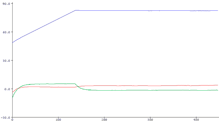
Tened en cuenta que el DMP necesita un periodo para empezar a funcionar. Al principio devolverá medidas imprecisas y, durante un tiempo irá haciéndose más estables. Lo normal es unos periodo de unos 15 segundos, aunque en algunos casos puede ser de hasta 40 segundos.

La gráfica anterior muestra la evolución de las variables yaw, pitch y roll, al encender Arduino. El eje X está escalado en décimas de segundo. Por lo que vemos que, en este caso, el sensor tarda unos 15 segundos en estabilizarse y dar mediciones válidas.
Calibrar el DMP
Para que las medidas del DMP sean totalmente precisas es necesario ajustar realizar una calibración para ajustar los valores de offset. Para esto tenemos este sketch, que nos proporciona los valores de offset de nuestro sensor. Es necesario ejecutarlo para cada MPU6050, ya que puede haber una gran variación de uno a otro.
// Arduino sketch that returns calibration offsets for MPU6050
//   Version 1.1  (31th January 2014)
// Done by Luis Ródenas <[email protected]>
// Based on the I2Cdev library and previous work by Jeff Rowberg <[email protected]>
// Updates (of the library) should (hopefully) always be available at https://github.com/jrowberg/i2cdevlib

// These offsets were meant to calibrate MPU6050's internal DMP, but can be also useful for reading sensors.
// The effect of temperature has not been taken into account so I can't promise that it will work if you
// calibrate indoors and then use it outdoors. Best is to calibrate and use at the same room temperature.

/* ==========  LICENSE  ==================================
 I2Cdev device library code is placed under the MIT license
 Copyright (c) 2011 Jeff Rowberg

 Permission is hereby granted, free of charge, to any person obtaining a copy
 of this software and associated documentation files (the "Software"), to deal
 in the Software without restriction, including without limitation the rights
 to use, copy, modify, merge, publish, distribute, sublicense, and/or sell
 copies of the Software, and to permit persons to whom the Software is
 furnished to do so, subject to the following conditions:

 The above copyright notice and this permission notice shall be included in
 all copies or substantial portions of the Software.

 THE SOFTWARE IS PROVIDED "AS IS", WITHOUT WARRANTY OF ANY KIND, EXPRESS OR
 IMPLIED, INCLUDING BUT NOT LIMITED TO THE WARRANTIES OF MERCHANTABILITY,
 FITNESS FOR A PARTICULAR PURPOSE AND NONINFRINGEMENT. IN NO EVENT SHALL THE
 AUTHORS OR COPYRIGHT HOLDERS BE LIABLE FOR ANY CLAIM, DAMAGES OR OTHER
 LIABILITY, WHETHER IN AN ACTION OF CONTRACT, TORT OR OTHERWISE, ARISING FROM,
 OUT OF OR IN CONNECTION WITH THE SOFTWARE OR THE USE OR OTHER DEALINGS IN
 THE SOFTWARE.
 =========================================================
 */

// I2Cdev and MPU6050 must be installed as libraries
#include "I2Cdev.h"
#include "MPU6050.h"
#include "Wire.h"

///////////////////////////////////   CONFIGURATION   /////////////////////////////
//Change this 3 variables if you want to fine tune the skecth to your needs.
int buffersize=1000;     //Amount of readings used to average, make it higher to get more precision but sketch will be slower  (default:1000)
int acel_deadzone=8;     //Acelerometer error allowed, make it lower to get more precision, but sketch may not converge  (default:8)
int giro_deadzone=1;     //Giro error allowed, make it lower to get more precision, but sketch may not converge  (default:1)

// default I2C address is 0x68
// specific I2C addresses may be passed as a parameter here
// AD0 low = 0x68 (default for InvenSense evaluation board)
// AD0 high = 0x69
//MPU6050 accelgyro;
MPU6050 accelgyro(0x68); // <-- use for AD0 high

int16_t ax, ay, az,gx, gy, gz;

int mean_ax,mean_ay,mean_az,mean_gx,mean_gy,mean_gz,state=0;
int ax_offset,ay_offset,az_offset,gx_offset,gy_offset,gz_offset;

///////////////////////////////////   SETUP   ////////////////////////////////////
void setup() {
  // join I2C bus (I2Cdev library doesn't do this automatically)
  Wire.begin();
  // COMMENT NEXT LINE IF YOU ARE USING ARDUINO DUE
  TWBR = 24; // 400kHz I2C clock (200kHz if CPU is 8MHz). Leonardo measured 250kHz.

  // initialize serial communication
  Serial.begin(115200);

  // initialize device
  accelgyro.initialize();

  // wait for ready
  while (Serial.available() && Serial.read()); // empty buffer
  while (!Serial.available()){
    Serial.println(F("Send any character to start sketch.\n"));
    delay(1500);
  }
  while (Serial.available() && Serial.read()); // empty buffer again

  // start message
  Serial.println("\nMPU6050 Calibration Sketch");
  delay(2000);
  Serial.println("\nYour MPU6050 should be placed in horizontal position, with package letters facing up. \nDon't touch it until you see a finish message.\n");
  delay(3000);
  // verify connection
  Serial.println(accelgyro.testConnection() ? "MPU6050 connection successful" : "MPU6050 connection failed");
  delay(1000);
  // reset offsets
  accelgyro.setXAccelOffset(0);
  accelgyro.setYAccelOffset(0);
  accelgyro.setZAccelOffset(0);
  accelgyro.setXGyroOffset(0);
  accelgyro.setYGyroOffset(0);
  accelgyro.setZGyroOffset(0);
}

///////////////////////////////////   LOOP   ////////////////////////////////////
void loop() {
  if (state==0){
    Serial.println("\nReading sensors for first time...");
    meansensors();
    state++;
    delay(1000);
  }

  if (state==1) {
    Serial.println("\nCalculating offsets...");
    calibration();
    state++;
    delay(1000);
  }

  if (state==2) {
    meansensors();
    Serial.println("\nFINISHED!");
    Serial.print("\nSensor readings with offsets:\t");
    Serial.print(mean_ax);
    Serial.print("\t");
    Serial.print(mean_ay);
    Serial.print("\t");
    Serial.print(mean_az);
    Serial.print("\t");
    Serial.print(mean_gx);
    Serial.print("\t");
    Serial.print(mean_gy);
    Serial.print("\t");
    Serial.println(mean_gz);
    Serial.print("Your offsets:\t");
    Serial.print(ax_offset);
    Serial.print("\t");
    Serial.print(ay_offset);
    Serial.print("\t");
    Serial.print(az_offset);
    Serial.print("\t");
    Serial.print(gx_offset);
    Serial.print("\t");
    Serial.print(gy_offset);
    Serial.print("\t");
    Serial.println(gz_offset);
    Serial.println("\nData is printed as: acelX acelY acelZ giroX giroY giroZ");
    Serial.println("Check that your sensor readings are close to 0 0 16384 0 0 0");
    Serial.println("If calibration was succesful write down your offsets so you can set them in your projects using something similar to mpu.setXAccelOffset(youroffset)");
    while (1);
  }
}

///////////////////////////////////   FUNCTIONS   ////////////////////////////////////
void meansensors(){
  long i=0,buff_ax=0,buff_ay=0,buff_az=0,buff_gx=0,buff_gy=0,buff_gz=0;

  while (i<(buffersize+101)){
    // read raw accel/gyro measurements from device
    accelgyro.getMotion6(&ax, &ay, &az, &gx, &gy, &gz);

    if (i>100 && i<=(buffersize+100)){ //First 100 measures are discarded
      buff_ax=buff_ax+ax;
      buff_ay=buff_ay+ay;
      buff_az=buff_az+az;
      buff_gx=buff_gx+gx;
      buff_gy=buff_gy+gy;
      buff_gz=buff_gz+gz;
    }
    if (i==(buffersize+100)){
      mean_ax=buff_ax/buffersize;
      mean_ay=buff_ay/buffersize;
      mean_az=buff_az/buffersize;
      mean_gx=buff_gx/buffersize;
      mean_gy=buff_gy/buffersize;
      mean_gz=buff_gz/buffersize;
    }
    i++;
    delay(2); //Needed so we don't get repeated measures
  }
}

void calibration(){
  ax_offset=-mean_ax/8;
  ay_offset=-mean_ay/8;
  az_offset=(16384-mean_az)/8;

  gx_offset=-mean_gx/4;
  gy_offset=-mean_gy/4;
  gz_offset=-mean_gz/4;
  while (1){
    int ready=0;
    accelgyro.setXAccelOffset(ax_offset);
    accelgyro.setYAccelOffset(ay_offset);
    accelgyro.setZAccelOffset(az_offset);

    accelgyro.setXGyroOffset(gx_offset);
    accelgyro.setYGyroOffset(gy_offset);
    accelgyro.setZGyroOffset(gz_offset);

    meansensors();
    Serial.println("...");

    if (abs(mean_ax)<=acel_deadzone) ready++;
    else ax_offset=ax_offset-mean_ax/acel_deadzone;

    if (abs(mean_ay)<=acel_deadzone) ready++;
    else ay_offset=ay_offset-mean_ay/acel_deadzone;

    if (abs(16384-mean_az)<=acel_deadzone) ready++;
    else az_offset=az_offset+(16384-mean_az)/acel_deadzone;

    if (abs(mean_gx)<=giro_deadzone) ready++;
    else gx_offset=gx_offset-mean_gx/(giro_deadzone+1);

    if (abs(mean_gy)<=giro_deadzone) ready++;
    else gy_offset=gy_offset-mean_gy/(giro_deadzone+1);

    if (abs(mean_gz)<=giro_deadzone) ready++;
    else gz_offset=gz_offset-mean_gz/(giro_deadzone+1);

    if (ready==6) break;
  }
}
Ejemplo con RTIMULIB-Arduino
Otra opción para la lectura del sensor es emplear la librería RTIMULIB-Arduino, que permite crear un sistema AHRS (Attitude Heading Reference Systems) y funciona con una gran variedad de sensores. Vimos como emplear esta librería en esta entrada.
Descarga el código
Todo el código de esta entrada está disponible para su descarga en Github.

